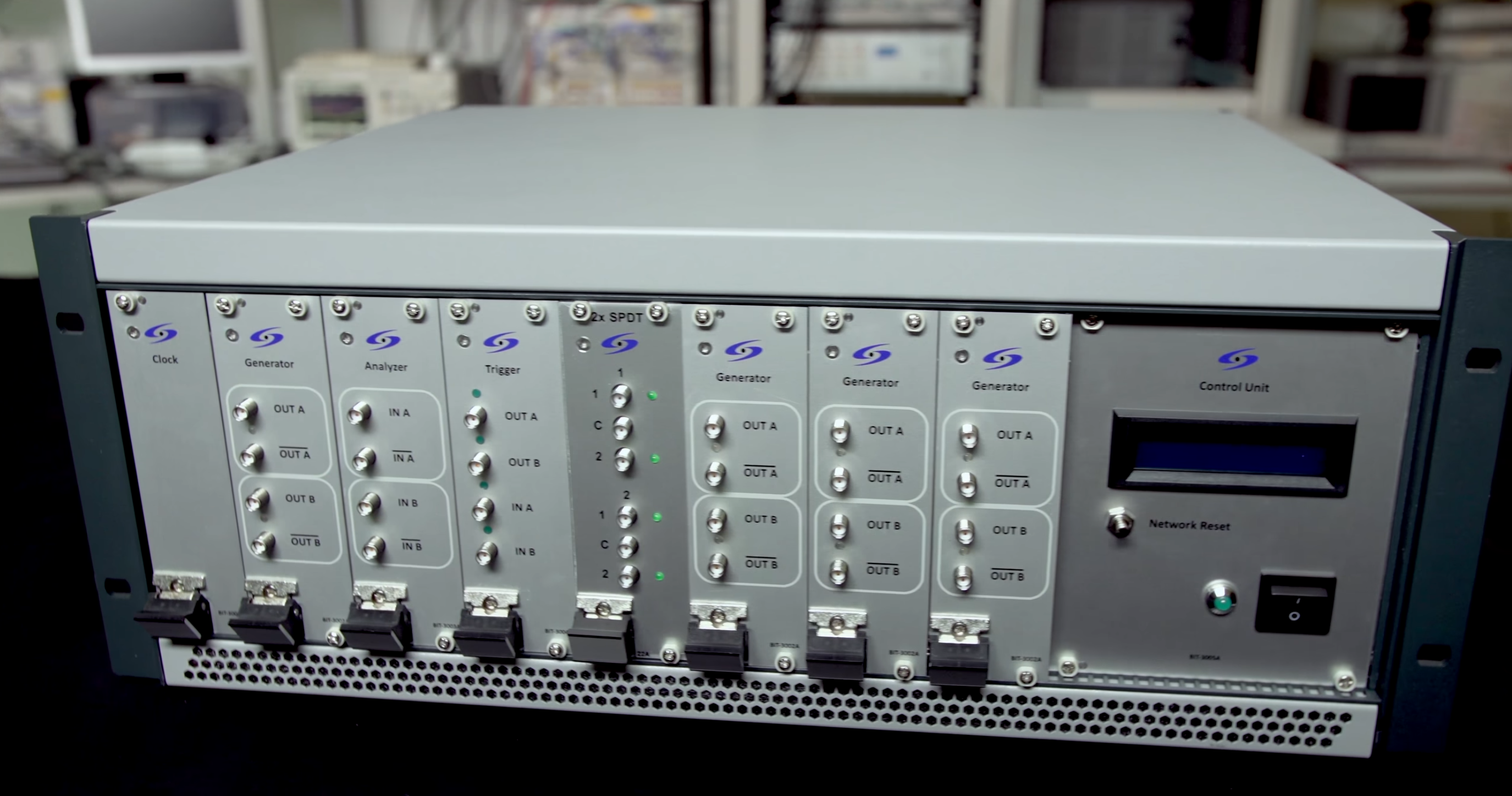
Dynamic Sequencing Generator and Analyzer (DSGA) and Automated High-Bandwidth Switch System
Receiver tests in the lab are often too “ideal”. Real silicon does not sit forever in a steady high‑speed lane sending a single pattern. It flips between high‑speed bursts and low‑power states, exchanges sideband control, reconfigures lanes, reports counters and status, then dives back into data again. Two hardware pieces made those real behaviors testable in an automated way: a Dynamic Sequencing Generator & Analyzer (DSGA) and a modular high‑bandwidth switching system. Classic AWGs (Arbitrary Waveform Generators) and BERTs (Bit Error Rate Testers) are great at stressed data (jittered PRBS, de‑emphasis, ISI). They are not built to script low‑speed protocol “glue” or to read device feedback while stress is applied. The DSGA plus switching closes that gap.
Why a “Low-Speed” Generator Matters
High‑speed gear produces stressed patterns very well. It struggles when the test script needs protocol moves: enter a test mode, switch to low‑power (LP), send a short command frame, read a PWM counter, then return to high‑speed (HS) and inject jitter—repeat. MIPI M‑PHY and D‑PHY receiver work in particular mix HS bursts and LP signaling tightly. Without a tool that can generate and decode LP traffic you either simplify the sequence (and miss issues) or spend a lot of time hand‑building partial setups.
The DSGA couples protocol sequencing with physical layer stress. It can:
- Generate deterministic low‑speed control patterns and mode‑entry sequences.
- Trigger high‑speed instruments for synchronized HS bursts.
- Capture and decode PWM or framed status returns (e.g., frame counters, error counters) from the Device Under Test (DUT).
- Provide timing hooks so stressed waveform injection aligns with real protocol state, not an approximate guess.
Result: jitter, noise and amplitude changes are applied only while the receiver actually expects HS data. Then control drops back to LP to move the DUT to the next condition and read fresh counters. Stress is no longer a blind, free‑running waveform; it is aligned to real protocol state.
Automation & Integration
Automated scripts (the same receiver validation flow used for broader high‑speed testing) drive protocol states, arm the high‑speed path, run measurements (eye diagram, BER, jitter breakdown), read counters and move on. No manual register poking or re‑cabling. Large test sweeps (lanes, voltage corners, equalization settings) run unattended instead of consuming bench time.
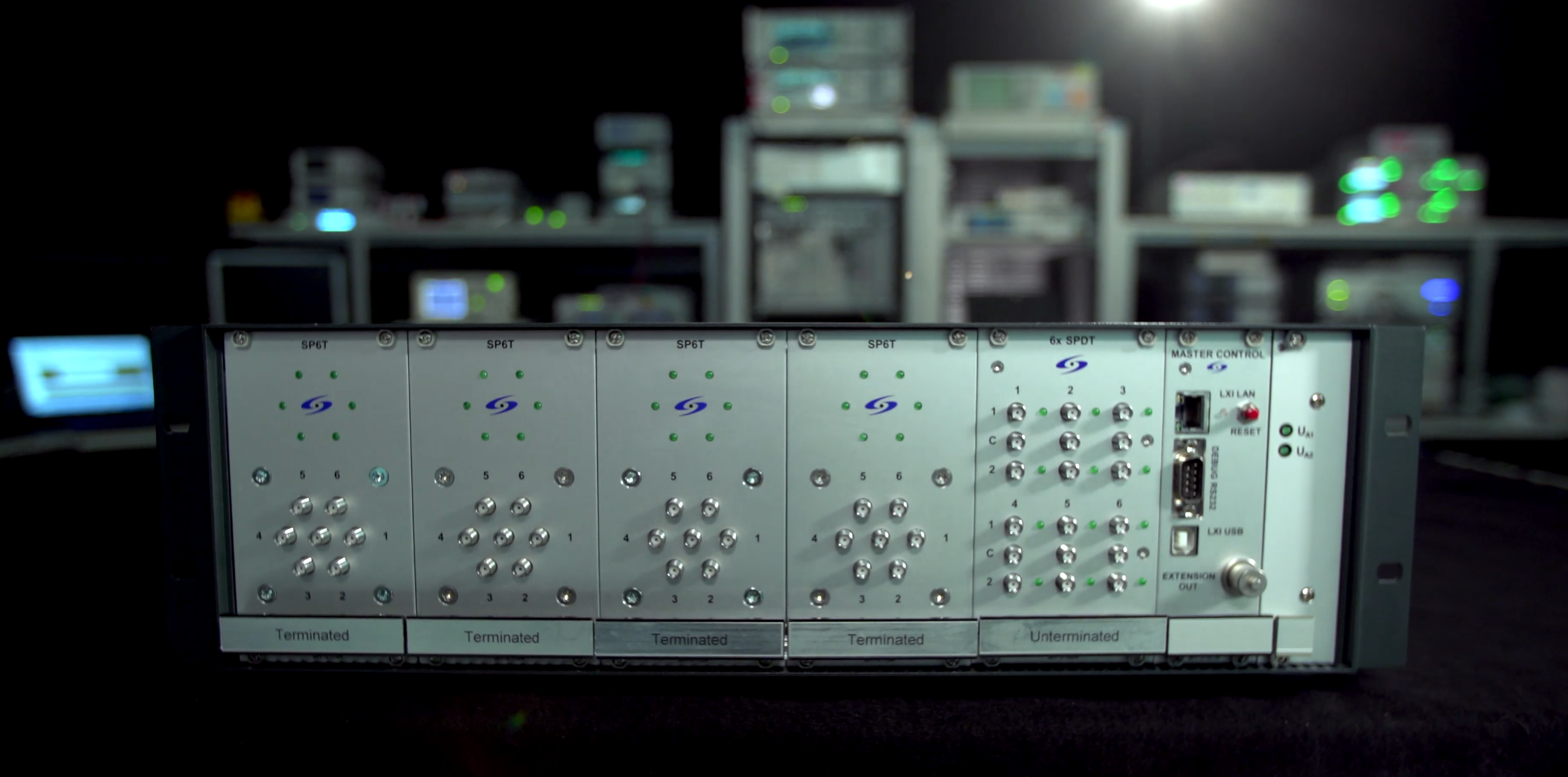
The Switching Challenge
Protocol‑aware automation still stalls if someone has to keep changing cables. Manual lane swaps add variation (skew, seating quality), wear out connectors and slow regression runs. With multi‑lane interfaces (MIPI, HDMI, USB Type‑C, etc.) most of a long test plan can turn into cable handling.
The switching system offers 2:1, 4:1, 6:1 or 8:1 modules up to 26.5 GHz. A five‑slot chassis scales lane count and signal mix. Software control inside the same automation framework lets a script:
- Select any lane or path on demand (RX/TX/cable/fixture permutations).
- Iterate through ports without physical intervention.
- Maintain consistent insertion loss & phase characteristics across runs.
- Reduce wear on expensive instrument and DUT connectors.
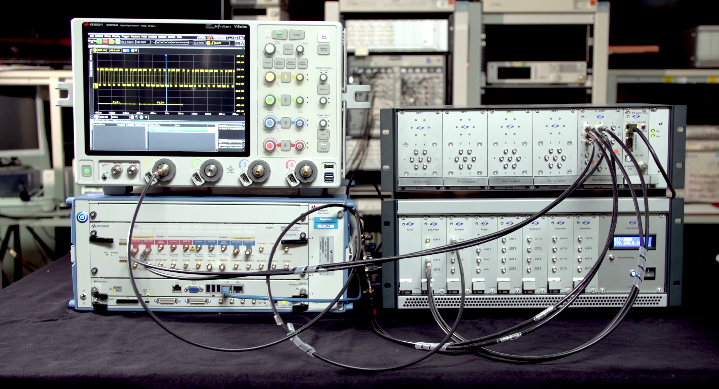
Putting It Together: State-Aware, Scalable Test Rig
Typical integrated flow:
- DSGA programs DUT into the desired test or stress mode (LP signaling, register writes).
- Switch system routes the appropriate lane set through calibration fixtures to the AWG/BERT.
- High‑speed instruments inject controlled impairments (random/deterministic jitter, voltage drop, ISI) while DSGA timestamps protocol state boundaries.
- Measurement algorithms capture eye, BER, jitter spectra; DSGA simultaneously reads DUT counters for correlation.
- Automation script advances to the next test condition, reconfigures switch paths as needed, and repeats.
Outcome: a fully automated, state‑aware high-speed digital receiver test platform with very little human touch time.
Engineering Work
Work spanned board and module design, signal integrity measurements on characterization fixtures, firmware development, commissioning and integration into existing receiver automation products. Test descriptions abstracted HS/LP interleaves and path permutations so growing a regression set meant changing metadata, not rewriting scripts.
Why It Was Interesting
High‑speed digital work is fun partly because of the gear: scopes, BERTs, AWGs, analyzers—all great at their piece. The interesting part here was stitching protocol knowledge, RF integrity, sequencing, mechanics and automation into one harness. That turned a manual compliance list into a repeatable platform that keeps pace with new silicon. The sequencing generator plus switching does not replace the high‑end instruments; it makes them act in context—stressing only when it matters and collecting receiver reaction with tight timing.